A box, and water that stays in
The subsystems were packed into a real enclosure and split to fit the printer, and the first printed flavor reservoir held water without weeping.
The enclosure
At the start the enclosure was three README files with no geometry.
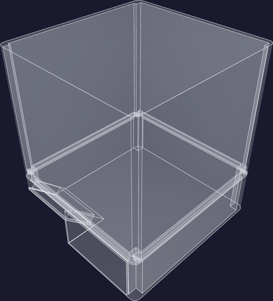
It is now a parametric PETG box with 3 mm walls that sizes itself to the bounding box of its contents, with every internal subsystem placed in shared coordinates inside it — cold core, compressor, condenser, valve trays, pumps, displays. Four internal zones are named: cold core at back-bottom, electronics at back-top, funnel over pumps at front-top, refrigeration at front-bottom.
The box exceeds every print bed available. On 17–18 June it was split into two halves that telescope and bolt together on four M3 corner cross-pins, and reduced-size test coupons of both halves were exported to prove the joint before a full print. A second, deeper and narrower variant appeared on 20 June with the cold core, compressor and funnel rotated a quarter turn. Both variants stand at the close.
Water that stays in
On 29 May a small printed test cup with a new wall, infill and ironing recipe held water on the first attempt.
On 30 May the left flavor reservoir printed with that recipe, assembled into a freshly printed full-size insulation shell with its bulkhead and printed flexible gaskets, and held water for several hours with no weep. The insulation shell printed full-size the same day and warped at the corners; a reprint came off whole in fourteen hours with no warp.
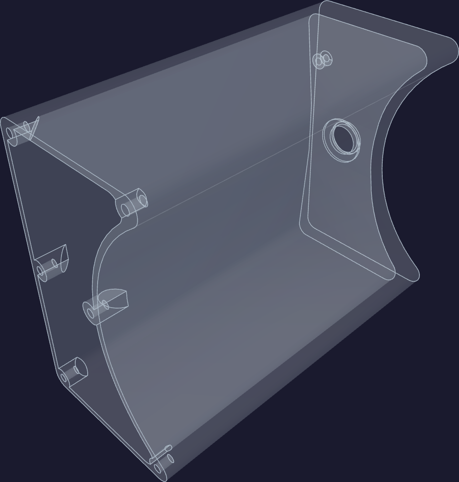
The recipe is written down and is independent of filament brand.
The epoxy liner was dropped on 29 May, one day after the epoxy kit was delivered. Bare printed PETG is the food-contact wetted surface, the wall thinned to 3 mm, and an acceptance test replaces the liner: acidic simulant, ten days at 40 °C, migration weight plus a taint check.
Two touchscreens
The design called for a pneumatic air switch to pick the flavor and a small round display on a cord. Both are gone from the appliance.
The faucet head now carries a 1.47-inch capacitive touch screen that shows the flavor and switches it by touch, with no separate button. The appliance's front face carries a fixed 4.3-inch 800×480 touchscreen as the settings surface, set into an angled facet cut across the front corner. Both boards arrived, both got new firmware trees, and the large panel was brought up tear-free with double-buffered direct panel driving.
The valve manifold
The manifold was a valve-state truth table in a document. It is now four printed cradle trays holding twelve solenoid valves against modelled fittings — source-select, bag circuit, bag-in-box gates and nozzle gates — with the tray grouping drawn as its own diagram. Eight more solenoids arrived on 17 June, bringing the count to twelve with four spare.
A servo-actuated ball valve was modelled and bench-tested on a spare controller. The solenoids held.
A controller board on paper
By 10 June there was a plan to replace the whole module stack — controller, two I/O expanders, two driver arrays, two motor drivers, clock, two relays and on-board power regulation — with one 100 × 100 mm four-layer board. By the 16th the schematic was captured in code, about 40 parts and 94 connections, emitting a standard netlist, with all parts auto-placed headlessly.
The project's own documents call the layout a rough first pass. Nothing was ordered in these four weeks.
A rework bench
A vacuum desoldering gun arrived on 15 June after solder braid failed to clear plated through-holes, alongside low-melt removal alloy, polyimide tape, precision tweezers, a fine chisel tip, fine solder, a ten-tip assortment, a ratcheting crimper and syringe flux. The occasion was migrating pre-soldered headers on stock modules from friction connectors to keyed locking ones. The first use was filmed on 19 June and published as the seventh channel video.
Level sensing
The float rod inside the pressure vessel changed from a welded part to a blind register drilled 9/64 inch by 0.10 inch deep into the quarter-inch end cap, capturing the rod without breaching the 90 PSI wall. Cobalt drill bits, forty pieces of 1/8-inch 316 stainless rod, and a benchtop metal-cutting band saw were bought to do it in-house.
The harvested magnet float became a purpose-printed buoyant puck with a neodymium ring magnet sealed inside mid-print.
No tank was welded and no pressure test was run in these four weeks. A dye-penetrant crack inspection was added ahead of the hydro test and its three chemicals bought.