First metal, and a public face
The fallback vessel design was archived, stainless was tapped and welded by hand for the first time, and the project got a live website and a YouTube channel.
The vessel
Two geometries were live at the start: a commodity 5-inch stainless tube capped with laser-cut plates, and a sheet-formed racetrack body with its press dies, dishing dies, milled pot and atomizer nozzle.
The racetrack program is gone — thirteen part folders and about 118,000 lines removed, preserved under archive tags. Working pressure closed at 90 PSI, up from 70, with a named regulator and relief valve.
One of the forty required NPT threads was hand-tapped into a 316L end cap on 3 May. The result was recorded on video and the thread depth called inconclusive. The fixture for the remaining thirty-nine is still an open design step.
Practice welding ran on 304L test vessels through the period, ending with three consecutive clean pull-aways on camera on 22 May. No production vessel was welded and no hydrostatic test was run.
The cold core
At the start this was one folder — a foam shell assuming off-the-shelf 1 L bladders in side pockets.
It is now a nine-script subsystem: inner and outer foam shells, two end caps with lids, a three-piece copper plug stack, a coil-winding mandrel, a relief-valve shroud, a support ring, channels for magnetic level sensors, and two rigid PETG flavor reservoirs with sloped drain floors, vents, gaskets and a stainless float rod. About 80,000 lines of new geometry.
The flexible bladders are gone. The first flavor reservoir printed in food-contact PETG on 22 May.
The faucet
The faucet began as an unmodelled harvested valve body. It is now a measured 3D reference of that body, a printed shell, a mounting plate, a TPU gasket and o-ring, and a laser-cut stainless under-counter plate — ten of those plates were delivered on 14 May.
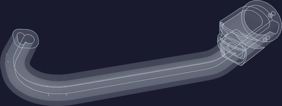
The print log carries fifteen attempts inside these four weeks. The first six produced no usable part: two clogs above the hot end, a run of nozzle-calibration failures, a print that began laying air at layer 15, one that finished full of gaps, and one the log leaves without an outcome. The seventh worked — "the most recent PET-CF print worked beautifully" — on a 0.6 mm tungsten-carbide nozzle delivered on 9 May, with the supports printed in the model's own material so they broke away clean. The eighth failed when a tall support tower leaned over and fused into the peak of the faucet. The ninth, with a 20 mm brim under every tower and supports rooted only in the build plate, came out whole.
The shell was then split into three slip-fit pieces and the joint clearances tuned by pull test across attempts 10 to 15 — zero clearance would not seat, half a millimetre was "far too much of one", and both joints converged near 0.05 mm before the looser of the two was eased back to about 0.08.
The broken extruder on 4 May was followed the same day by an order for a replacement and a second H2C printer.
A public face
homesodamachine.com went live on 29 April: a Node site on Render with a Postgres database, serving a landing page and signup, a browser 3D and CAD viewer, a daily feed, and an installable app with push notifications.
Six videos published between 4 May and 22 May. The edit process moved from iMovie to scripted waveform audio sync, speech-driven scene segmentation, burned-in captions, overlays and generated sound effects.
The build sequence
Eleven production procedures were written, covering the full chain: pressure vessel fabrication, refrigerant loop conversion, cold core assembly, two off-appliance bench builds, enclosure mechanical, internal plumbing, wiring, firmware commissioning, an acceptance test and burn-in, and finish, pack and ship. They cross-reference each other by input and output state and name their own open questions — hydro-test pass criteria and failure handling are undefined.
Safety
A sheet-metal shroud encloses the compressor's terminal block and start relay. A 77 °C thermal fuse sits in series with the compressor's AC leg. A combustible-gas sensor mounts low on the cabinet's rear wall, where the refrigerant pools. An audible alarm and a self-testing ground-fault unit sit behind the front panel rather than in the cord.
The front page
The README went from 413 lines titled "Soda Flavor Injector" to 31 lines titled "Home Soda Machine", pointing at the appliance, the site, and a two-chapter project biography. The working prototype's parts list, cost breakdown and eight photos were retired to tags — the prototype now lives in the kitchen rather than the repository.