Compressor cable follows the valve-bank gap below the funnel
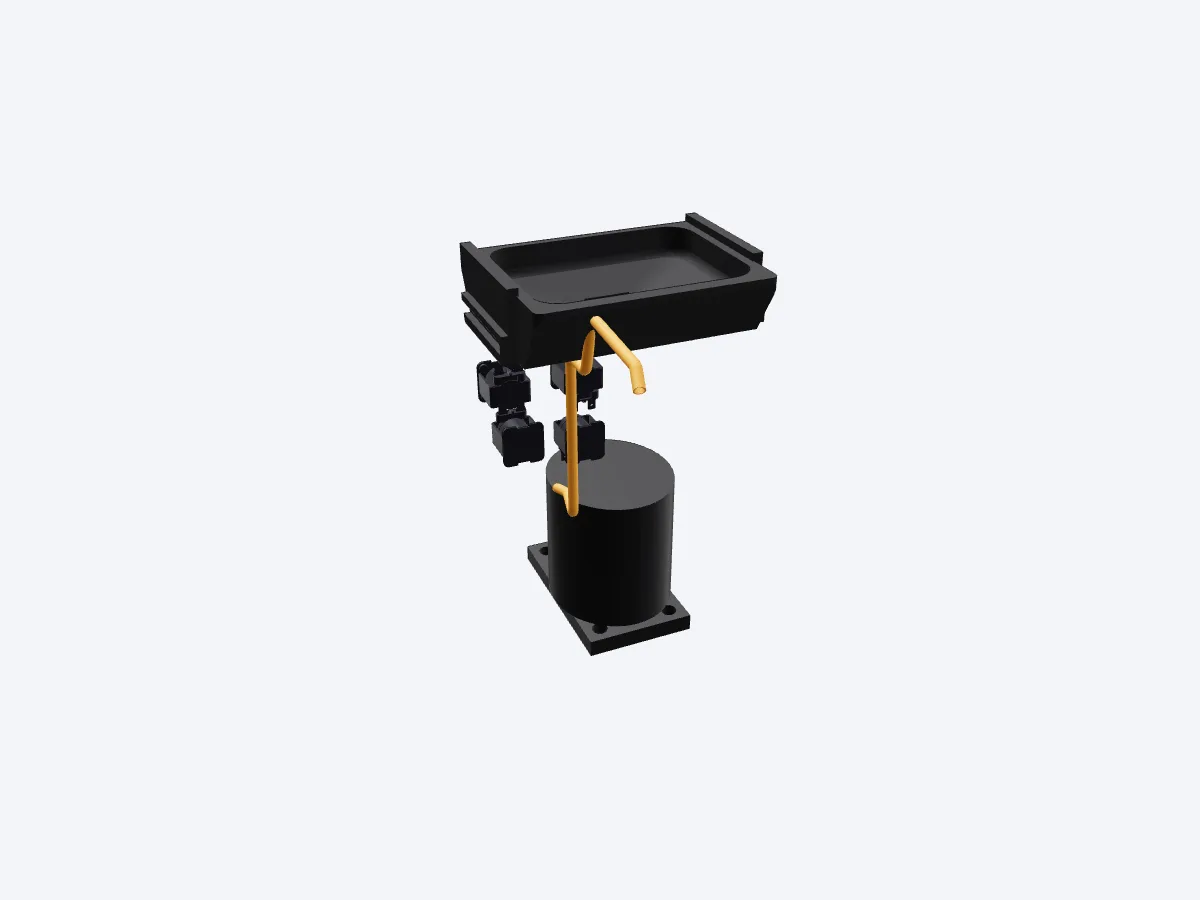
 Shared cable
BeforeAfter
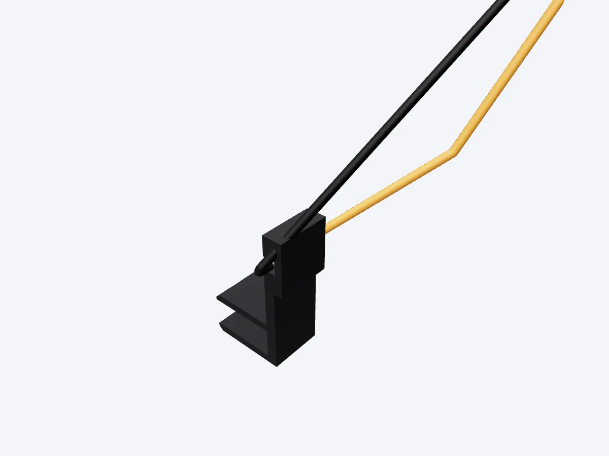
 Splice region
BeforeAfter
The shared cable and its end fanouts clear the installed hardware and nearby wires. The fuse leads reach insulated splices beside the power box.
The shared compressor cable runs below the funnel frame, between the existing valve banks and into the compressor bay. Its three insulated cores keep their spacing through the bends. Fifteen neighboring wire paths are dressed clear of the cable. The hardware arrangement is retained.
The compressor earth uses the downward-facing ring lug. The thermal fuse's reference shows only its first 3 mm of straight lead; the installed model also carries the dressed leads to two insulated splice regions. The short hot link from the fuse passes below the neutral and earth fanout. Estimated donor landings sit beside the retained power-cover envelope.
The modeled longest core is approximately 529 mm. Preparation stock is 600 mm, with the ends trimmed after routing. The two dressed fuse leads fit within the reference's 35 mm and 20 mm lengths.
The compressor-cable review records valid native bodies, separate cores, and no hardware or neighboring-wire intersections for this cable and its fuse link. These are proposed installed arrangements using the model's dimensional allowances.
Derek: “Agreed you can handle that.”